1. Introduction
Fused Deposition Modeling (FDM), also referred to as Fused Filament Fabrication (FFF), is the most widely adopted 3D printing technology in use today. By extruding thermoplastic filament layer by layer to create complex geometries, FDM has evolved from a prototyping tool into a full-fledged digital manufacturing solution for end-use parts, fixtures, tooling, and beyond.
For engineers, product developers, and manufacturing professionals, FDM offers distinct advantages in terms of material variety, design freedom, affordability, and scalability. But to leverage these benefits effectively, it is essential to understand the process mechanics, materials science, design limitations, and production best practices behind the technology.
This white paper provides an in-depth technical overview of FDM, exploring how and when to use it, how it compares to other 3D printing processes, and the design principles required to achieve optimal performance.
2. FDM Technology Explained
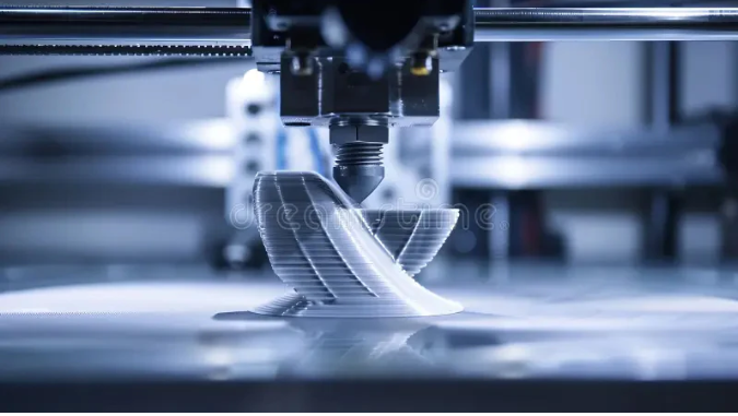
FDM is a form of additive manufacturing where thermoplastic filament is extruded through a heated nozzle, depositing material layer by layer according to a digital CAD model. The filament is softened just past its glass transition temperature, allowing for precise flow and solidification upon cooling.
The process requires:
- A spool of filament
- An extrusion head capable of motion in three axes (X, Y, Z)
- A heated build plate or enclosed chamber
- A slicer program to convert CAD geometry into layer instructions (G-code)
The nozzle deposits molten polymer along a predetermined path. Upon deposition, the material bonds with the previous layer through a combination of thermal diffusion and pressure. This layered build structure results in anisotropic mechanical behavior and creates visible layer lines that may require post-processing.
3. Materials: Engineering-Grade Thermoplastics
FDM’s strength lies in its material versatility. Engineers can select from low-cost prototyping polymers to high-performance materials suitable for structural applications.
Standard Materials
- PLA: Easy to print, low warping, biodegradable. Low strength and thermal resistance.
- ABS: Stronger and more temperature-resistant than PLA. Moderate warping and good post-processing compatibility.
- PETG: A good middle ground between PLA and ABS. Food-safe, chemical-resistant, and low shrinkage.
- ASA: UV-resistant and stable outdoors. Used for functional and cosmetic parts.
Engineering-Grade
- Nylon (PA): High strength, wear-resistant, flexible. Hygroscopic; requires drying before printing.
- TPU: Flexible, impact-resistant, abrasion-resistant. Requires slower print speeds and retraction control.
High-Performance Polymers
- PEI (ULTEM™ 9085/1010): Flame-retardant, strong, chemically resistant. Requires heated chamber and high-temp nozzle.
- PEKK (Antero 800NA): Aerospace-grade, low outgassing, chemically inert.
Filled Composites
- Nylon 12CF, ABS CF10: Carbon fiber-reinforced for high stiffness and lightweight tooling.
Material choice affects dimensional stability, surface finish, cost, and post-processing compatibility. Selecting the right polymer for your application is key to successful FDM production.
4. FDM Design Guidelines for Manufacturability
To ensure part success in FDM, engineers must design around process-specific constraints. Common failure modes like warping, layer delamination, poor overhang quality, or dimensional inaccuracy can be mitigated with proper design.
Layer Height and Resolution
Typical layer heights range from 50–400 μm. Smaller layers yield finer detail, better curved surfaces, and tighter tolerance—but increase print time.
- 100–200 μm is a recommended compromise for surface finish and throughput.
- Vertical resolution is limited by layer height; horizontal resolution is limited by nozzle diameter (typically 0.4–0.5 mm).
Wall Thickness
Minimum recommended wall thickness is:
- 0.8 mm for supported walls
- 1.2 mm for unsupported walls
Thinner walls may print but lack strength and are prone to warping.
Holes and Pins
- Vertical holes often print undersized. Reaming or drilling post-print is recommended for critical fits.
- Pins under 5 mm diameter may break due to poor layer adhesion; consider using dowels.
Overhangs and Bridges
- Overhangs >45° require support.
- Bridges <5 mm can print unsupported, but sagging occurs beyond that span.
Corners and First Layer Adhesion
FDM prints round corners due to nozzle geometry. To minimize “elephant’s foot,” use chamfers or raised platforms.
Orientation and Strength
Due to the anisotropic nature of FDM, Z-axis strength is significantly lower than in-plane strength. Parts should be oriented to align the load path with the printed layers.
5. Post-Processing for FDM Parts
Post-processing can significantly enhance the mechanical and cosmetic properties of FDM parts:
- Sanding and polishing for smoother finishes
- Priming and painting for appearance and color matching
- Vapor smoothing (acetone for ABS) for glossy surfaces
- Drilling, tapping, and machining for functional fits
- Epoxy coating or plating for enhanced strength and surface uniformity
Post-processing should be considered during design to allow for tolerances, finishing access, and part orientation.
6. Industrial vs. Desktop FDM
Industrial FDM Systems
- ±0.2–0.3 mm accuracy
- Heated chambers, large build volumes (e.g., 900 x 600 x 900 mm)
- Use of high-performance materials (PEI, Nylon CF, PC)
- Designed for repeatability and unattended operation
Desktop FDM Systems
- ±0.5–1 mm accuracy
- Open or semi-enclosed frame
- Limited material support
- More manual calibration and maintenance
Industrial FDM is suited for manufacturing tools, jigs, and functional prototypes. Desktop systems serve for design validation, hobby projects, or light-duty parts.
7. Applications and Industry Use Cases
FDM is used across industries for both development and production.
Aerospace
- Lightweight brackets, cable routing clips, and ducting
- PEKK and PEI materials offer flame resistance and low outgassing
Automotive
- Assembly fixtures, prototype housings, gauge tools
- ABS-CF and PC blends enable strength and impact resistance
Healthcare
- Surgical guides, anatomical models, orthotics
- Biocompatible resins and sterilizable thermoplastics
Manufacturing
- Jigs, fixtures, check gauges, ergonomic tooling
- Tooling cost reduced by 70–90% vs. CNC/molding
Consumer Products
- Prototypes, short-run enclosures, and appliance internals
- Aesthetic models produced with ASA or PETG
8. Advantages of FDM
- Material Diversity: From flexible TPU to flame-resistant PEI, FDM covers a broad property range.
- Low Cost per Part: Ideal for low-volume runs and iterative development.
- Design Freedom: Internal features, lattice structures, and consolidation of assemblies.
- Office Friendly: Clean, safe, and scalable for both lab and production environments.
- On-Demand Manufacturing: No tooling required, enabling JIT production strategies.
9. Limitations and Challenges
- Lower Resolution: Compared to SLA or MJF, FDM lacks fine feature fidelity.
- Surface Quality: Visible layer lines; may require smoothing or machining.
- Anisotropic Properties: Weakness along the Z-axis due to poor interlayer bonding.
- Support Removal: May leave marks or require dissolvable supports (adds cost).
- Slow for Complex Parts: Print time increases with volume and detail.
FDM is not well-suited for parts requiring ultra-fine details, glass-clear transparency, or micron-level accuracy.
10. Comparing FDM to Other AM Technologies
| Metric | FDM | SLA | SLS | MJF |
| Surface Finish | Fair | Excellent | Good | Good |
| Detail Resolution | Moderate | Very High | Moderate | High |
| Strength | Good | Moderate | High | High |
| Isotropic Strength | No | No | Yes | Yes |
| Cost | Low | Moderate | Moderate | Moderate |
| Speed | Moderate | Slow | Fast | Fast |
| Build Volume | Large | Small–Medium | Medium | Medium |
| Support Removal | Required | Required | None | None |
Use FDM for cost-effective, functional prototypes and industrial-grade polymer parts that don’t require intricate detail or isotropic strength.
11. When to Choose FDM
Select FDM when:
- Your design has large features, durable geometry, or simple mating parts
- You’re working with common thermoplastics or high-strength polymers
- You want to validate form, fit, and function economically
- Surface finish is secondary or post-processing is acceptable
- Speed, repeatability, and cost matter more than resolution
Avoid FDM when:
- Very small, high-precision, or cosmetic parts are needed
- You require medical implants, full isotropy, or micro-scale features
12. Conclusion: FDM as a Scalable Manufacturing Tool
FDM is no longer just a prototyping technology. Its scalability, range of thermoplastics, and increasingly robust platforms have made it a valuable production asset for engineers across industries. When used within its capabilities, FDM offers unmatched cost-efficiency, material performance, and design flexibility—especially for short-run manufacturing, tooling, and industrial-grade prototypes.
With the right process control, material selection, and design strategy, FDM can produce parts that are not only fast and affordable—but fit for purpose in some of the world’s most demanding sectors.
Need help engineering your next part for FDM?
RapidMade offers design support, material consultation, and end-to-end production with both prototyping and industrial-grade FDM.
Visit rapidmade.com or contact us at info@rapidmade.com to get started.